
Getting a handle on hearing loops
 Hearing loops use magnetic induction to transmit audio broadcasts directly to telecoil-enabled hearing aids, providing clear audio to the hearing impaired without the use of a dedicated receiver. Jacob Harris explains.
The ability to hear audio clearly at a movie cinema, conference or even a train station is something most of us take for granted. But for people with a hearing impairment this can present a real challenge. Even when using a hearing aid, factors like background noise and the listener’s physical distance from the source can often make audio broadcasts difficult to hear clearly.
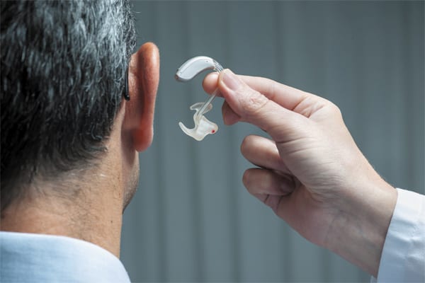
Hearing loops alleviate this difficulty by transmitting the audio signal directly to the listener’s (telecoil-enabled) hearing aid or cochlear implant. The technology works by amplifying an audio input signal and passing it through a loop of wire to create a magnetic field which is then picked up by the telecoil (T-coil) in the listener’s hearing aid.
ADVERTISEMENT
The wire loop is typically mounted at, or just below, floor level (but in some cases can also be mounted in the ceiling) and functions like the primary coil in a transformer, the secondary coil being the T-coil. This gives the wearer a clean, direct connection to the sound source – free from the losses, reverberation and ambient noise normally associated with hearing aid use.
“Induction loops provide a discreet listening solution for the hearing aid wearer because the only equipment needed to access the loop is their own hearing aid. There is no need to locate, wear or return portable receivers owned by the venue. This also benefits the venue owner as less hardware is needed and staff are not required to hand out, return, sanitise or charge any equipment,” says Audio Brands Australia (ABA) sales engineer Jeff Shoesmith. ABA is the Australian distributer of Univox.
Under the Building Code of Australia (BCA) and the New Zealand Building Code it is a legal requirement in Australia and New Zealand that hearing augmentation (commonly induction loops) be installed in practically any public space – from ticket booths at train stations to sports stadiums, theatres and schools – where an inbuilt amplification system is installed.
The AS60118.4-2007 is a rigorous standard for audio induction loop systems, and makes Australia internationally compliant in regard to field strength and audio quality for the hearing impaired. This defines the performance criteria of an induction loop system. Altronics sales manager Dean Stephens summarises the standard’s key points as:
- Field strength in the specified listening area shall be -20dB re 1A/m average i.e. 100mA/m long term average, using a 1kHz sinusoidal input, with a variation of +/-3dB short term peaks up to 400mA/m (0.125secs integration time).
- Environmental magnetic background noise shall be no higher than -40dB A-weighted (measured with the loop system off).
- Frequency response of the system shall be from 100Hz to 5,000Hz. The variation should be no more than +/-3dB from the value taken at 1kHz.
It should come as no surprise that there is an array of hearing loop related products on the market that adhere to the Standard. And although the system being installed may be up to scratch, ensuring the installation itself meets the required standards can be a complex undertaking.
Because the systems use a magnetic field to operate, metal objects in the environment can interfere with frequency levels in the audio transmission.
“When the magnetic field is set up to activate the loop it can generate eddy currents in metal objects in the room. Those currents can absorb some of the energy that would otherwise be used to activate the receiver in the hearing aid and these manifest as a reduction in the signal at different frequencies according to the characteristics of the room,” says Hills head of AV Richard Neale. Hills represents Williams in Sound in Australia.
“These reductions in frequency strength can be equalised by adding additional power into the loop in the frequencies affected by the metal. Any brand of loop driver is going to suffer from metal loss or metal interference in a room which has a lot of metal furniture in it, concrete reinforcement in the floor or any other significant metal structure.”
Integrators installing loop systems also need to evaluate levels of electromagnetic interference (EMI) in the space. EMI can be caused by electrical systems and create a low frequency buzz or hum in the listener’s T-coil. There are several ways for a skilled installer to mitigate the effects of EMI.
“Prior to installation, a field strength meter can be used to measure the level of environmental electromagnetic background noise present in the space. This is done to ensure the loop listeners receive clear audio, free from distracting hums and buzzes. High current electrical cables, switchboards, substations and lighting dimmers can be sources of noise. If the measured noise exceeds the specified levels, the client should be advised and the noise rectified at the source.”
Jeff Shoesmith adds, “when quoting new-build projects, integrators should ensure this step is carried out prior to the commencement of loop installation, once all electrical services in the space have been commissioned.”
The figuration of the loop itself is also an important consideration. Narrow areas of low signal (null zones) occur directly over the loop cable. In an installation where the loop runs around the perimeter of the room, this often won’t have a great impact on the system’s performance. But, as Richard explains, in large areas where maintaining even field strength is an issue, integrators also need to be mindful of potential null zones.
“If the loop is too big the field strength will not be even all across the loop. This will cause the performance to vary depending on where a person is situated inside the loop and of course that’s not acceptable. There are ways of getting around that though,” says Richard
“A multi-turn loop, for example, will make each segment of the loop smaller and that can even out the field strength but it can also create little null patches where the loop crosses itself. If the loop’s in a cinema and the null is up and down the aisle, that’s not really a problem because no one’s going to sit there to watch the movie. But if it’s a flexible space a null is going to cause problems. In those situations integrators should look at solutions like multi-channel loop amplifiers and phased arrays to cover a space evenly,” says Richard.
Because magnetic fields are not constrained by physical structures such as walls and ceilings, the audio signal can spill outside of the loop area and still be audible for a considerable distance around it. In many situations this isn’t an immediate problem but when installing induction loops into buildings like courtrooms, schools or conference centres where adjacent rooms are also using the technology or where live music is being performed (spill can also cause equipment such as electric guitars and dynamic microphones to produce feedback) it is imperative that loop spill is mitigated. For these applications a slightly more complex configuration such as a phased array or cancellation loop may be required.
Whatever loop figuration is being installed, close attention needs to be paid to the wire position, current direction and preparation of the surface if optimum coverage and performance are to be achieved.
“If copper foil is being used under carpet, the nearby floor surface should be swept, vacuumed and coated with a sealant prior to foil and warning tape being laid, to protect the copper from degradation over time by the alkalis present in the concrete. If circular copper wire is being installed into a saw cut in the surface of the concrete, the installer should check that the cable insulation is designed for ‘direct burial’. XLPE and some HDPE insulation is best in this situation,” says Jeff Shoesmith.
“To keep circuit inductance down and minimise unwanted electromagnetic crosstalk into nearby cables, the loop feeder cable (used for connecting the loop amplifier to the loop layout) should be a reasonably tightly twisted pair, and must match the cable spec nominated in the software design. If there are any major differences, the system designer must be advised to ensure the design is not compromised.”
The last thing and integrator needs after installing an induction loop in a new building is for the system to be damaged during carpet installation. Jeff outlines a few precautions an integrator can take to prevent damage going unnoticed.
“Once the loop layout and feeder have been tested for continuity, connect the circuit between a low voltage plug pack and coil of a relay. The plug pack (via the loop) will energise the relay. Connect a loud buzzer or piezo screamer to the ‘Normally Closed’ relay contact. Should one of the following trades accidentally cut one of the loop cables, the relay will de-energise and sound the buzzer – alerting them that damage has been done and allow the loop installer to make repairs while the wiring is still accessible. Hearing about loop wire damage is never fun, but it’s way better than finding out after the floor finish has been completed and the furniture installed!”
-
ADVERTISEMENT
-
ADVERTISEMENT
-
ADVERTISEMENT
-
ADVERTISEMENT