
Thermal management: the HOT topic
Maintaining the temperature inside racks is critical to the proper functioning and survival of the circuits, and the best approach to thermal management is an integrated one.
Thermal design of equipment racks and enclosures is essential to ensuring the functionality of the equipment and system. You must understand and calculate when to vent a rack using natural convection and when to use fan-forced air.
There are two airflows in a thermal system: how the heat travels through the rack and how the air moves throughout the room. The interaction between them is important and must be considered when taking an integrated approach.
ADVERTISEMENT
All heat generated by equipment must first be removed from the rack, followed by the room removing all heat from every rack. Many installations don’t have the luxury of an air-conditioned environment, so consideration must be given to how the room itself will vent.
You want to be sure that whatever heat is removed from the rack will not substantially raise the room temperature.
For digital equipment, the room itself should be no warmer than 24ºC. This gives a 5ºC temperature difference between the room and the recommended 29ºC internal rack temperature for optimum equipment life.
Additionally, the cooler the room – as long as its temperature is above the dew point so that condensation does not occur – the fewer vents or fans you need.
In most integrated AV installations, the greatest heat load comes from power amplifiers while they are driven. However, an increasing number of devices produce a considerable amount of heat.
"The design of racks and thermal loading should take into account future expansion and changes," says Middle Atlantic president Bob Schluter.
Microprocessors, which are often embedded to do signal processing, emit greater heat from equipment than ever before. And the heat rises as the speed of these clocks increases. Couple that with the continuing miniaturisation of electronics and you can quickly see that the trend is for more heat to be generated for a given amount of equipment rack space.
This is also known as increased heat density. The service life of most equipment is reduced by excess heat, so it is vital to engineer its removal. The maximum recommended constant operating temperature for most equipment is 29ºC. Staying within this limit will help to achieve a long service life for the equipment in an enclosure.
Why 29ºC? Most studies have shown that for every 5º rise over 29ºC the life of digital equipment is reduced by about 40%. IT consultancy firm The Uptime Institute goes one step further: using the same temperature pattern, long-term reliability is reduced by 50%.
Clearly there is a need to control the temperature in electronic enclosures.
Electrical equipment performance reliability and life expectancy are inversely related to the component temperature of the equipment. Amplifiers, on the other hand, can accommodate higher temperatures, many operating at up to 43ºC.
Proper planning of the cooling air path inside a rack ensures that no hot spots occur and waste heat is effectively removed.
The most common flow in equipment drawing higher current is one that pulls cooler air in from the front and exhausts heated air at the rear or sides.
Simulation and real-world testing shows that moving air through a cabinet from bottom to top results in the lowest internal cabinet temperatures.
However, many amplifier designs take cabinet air through the rear and exhaust it at the front. This presents some special thermal design challenges.
Most other non-amplifier equipment with internal fans draw air in through the rear and exhaust at the sides. This recirculates the cabinet air, and care should be taken as to placement so that the natural convective rise of heat is not disturbed.
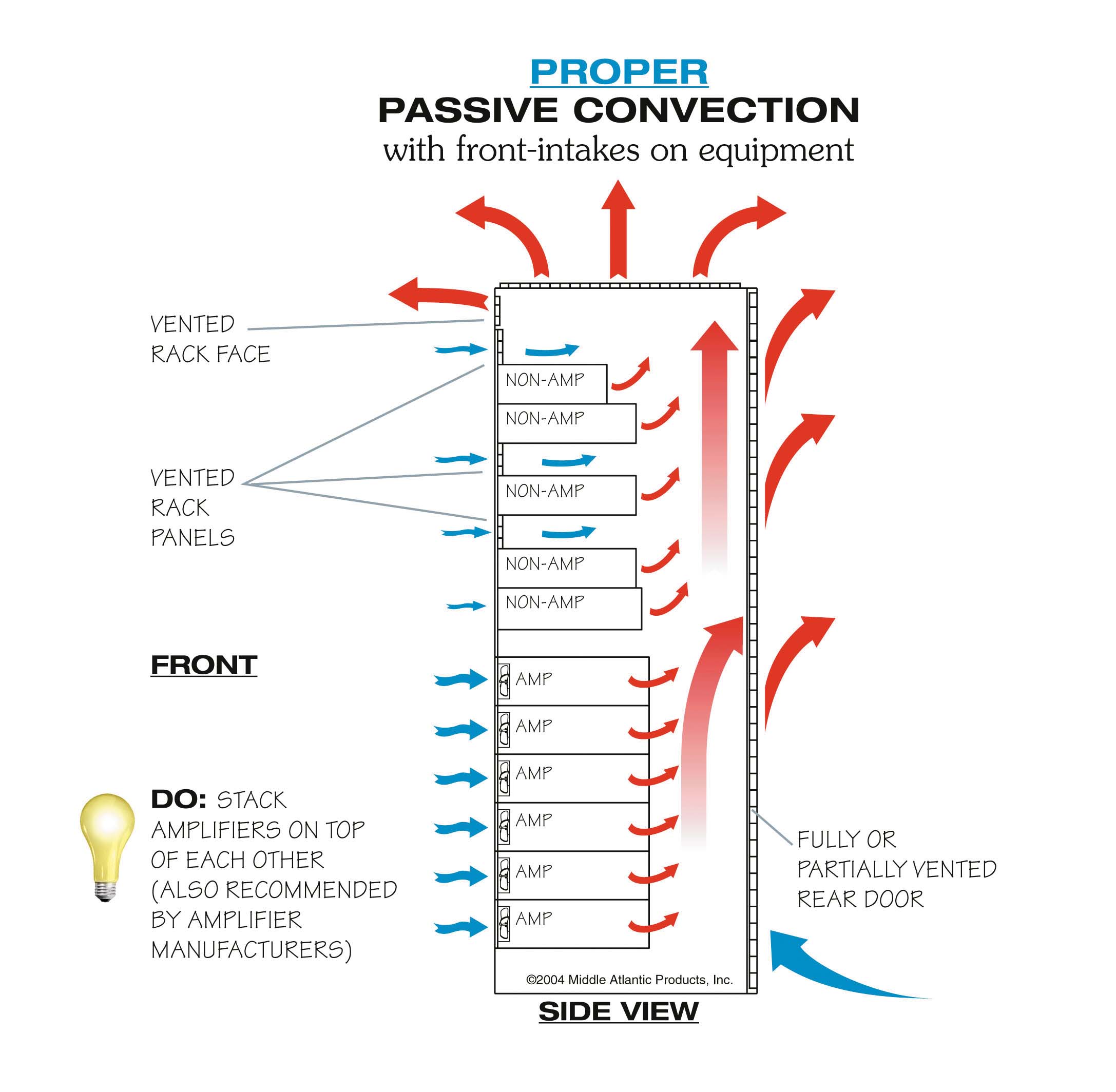
In an environment at normal room temperature a rack is able to dissipate 300-500W of heat through natural convection. This requires adequate vent openings at the bottom and top of the unit and an unimpeded airflow inside the rack.
The slow speed of airflow makes it nearly impossible to measure, and smoke tests have shown that air can enter and exit from the same vent. Equipment that passively vents sometimes has intake vents on the bottom, or vents on the top, so care must be taken not to block these with items of equipment stacked directly on top of each other.
Installers often put vents between pieces of equipment without regard to the recirculation of hot air. This can short-circuit the airflow, as the vents are too close to fans or heat sources.
For optimum performance, choose racks with vents built into the top face and ensure that a fully vented top has been installed. Installing a vented rear door in a passive cooling scenario is not necessarily required; it depends on the total heat produced in the rack.
To avoid starving the forced airflow, adequate intake venting area should be provided.
If the rack has a vented rear door, less rack-mount venting is required. Visual interpolation is adequate for approximating how many vented rack spaces are required in this situation.
Shelves are also an important component of internal airflow planning. Shelf surfaces that overhang the internal natural rise of heat should be vented. Any obstruction to airflow will raise the temperature in the lower portion of the rack, possibly creating a stratification zone. This should be avoided.
Using multiple fans mounted next to each other requires that they be checked regularly for proper operation. Once one fan stops functioning, it provides a short-circuit path for the airflow.
Don’t be fooled by thinking two fans will help. When one fails it acts as a vent near a fan and will not effectively remove heat from the enclosure. Care should be taken to ensure fans are operating properly to avoid this recirculation of heated enclosure air.
All fans fail over time. Of the many types available, ball-bearing fans outlast sleeve-bearing fans by about 50%. At 32ºC a ball-bearing fan will last about 55,000 hours, and a sleeve-bearing fan will quickly become inoperable at this temperature.
Because of the necessary bearings in fan assemblies, fans are more susceptible to failure than any other component. The most practical way of extending fan life is to use a proportional speed thermostatic fan control circuit.
Simply put, the faster a fan runs, the faster it wears out. Variable-speed fans are self-adaptive – they take into account changes in ambient temperature and the varying power dissipated by equipment. Even if filters are employed, the more unnecessary air that is forced through the rack will deposit dust in the electronics, reducing thermal transfer. Slowing the airflow down to the required amount will reduce the deposited dust.
All of the power consumed by communications equipment and computer products is converted to heat.
Calculating heat output for equipment other than amplifiers is simple: the more current drawn, the more heat is produced. At 240V, each ampere of current drawn produces 235W/h of heat output.
Amplifiers are not as straightforward, due to the different nature of circuit designs and other variables.
But the real-world heat output can be estimated by taking into consideration the amplifier’s output design, type of power supply, the program material that is played, ohms of the speaker load and at what average level the amplifier is to be driven.
At the low end of the thermal efficiency spectrum, Class A amplifiers average no more than 20% efficiency, which means 80% of the line current draw is converted to waste heat. It is extremely rare to find this class of amplifier in banks of equipment racks.
At the other end of the thermal efficiency spectrum, Class D amplifiers have up to 90% of the power draw converted to useable output watts, which means they generate only 10% waste heat. Class D amplifiers work more efficiently under loads, and actually generate more heat at idle than they do when driven.
Several amplifier manufacturers recognise the importance of thermal planning and publish excellent data on how much waste heat is generated for varying loads and input material. It is highly recommended to obtain this heat loss information from the manufacturers.
Amplifiers vary greatly in waste heat output. With heat loss information from the manufacturer in hand, to calculate total waste heat:
1. Obtain total waste heat output by combining the published waste heat W/h of all amplifiers in the rack.
2. Add up total measured amperage draw from all other equipment and multiply by 235 (total amperage x 235 = total W/h at 240V).
3. Combine W/h from steps 1 and 2 to obtain total for all equipment.
The design of racks and thermal loading should take into account future expansion and changes. The proper thermal design is often compromised when equipment is added to a rack.
Action should be taken if the interior rack temperature exceeds 29ºC. On some enclosure manufacturers’ tops, laser knockouts are provided for adding additional fans once all equipment has been installed. As stated earlier, the room needs to exhaust all heat produced by the equipment, so it is important that the facility be able to handle future expansion.
Bob Schluter has been active in the professional audio, video and computer industries in various capacities since 1976. After early involvement in electronic equipment design and recording studios, and 25 years as president and chief engineer of Middle Atlantic Products, Bob is designing next-generation enclosure systems and thermal control products.
-
ADVERTISEMENT
-
ADVERTISEMENT
-
ADVERTISEMENT
-
ADVERTISEMENT