
How does power quality affect AV systems?
Power quality in low-voltage distribution isn’t going to get better. Phil Kreveld outlines the issues for AV systems.
Younger teenagers who, by some miracle, have not subjected themselves to headphones blasting at 100dB for long periods can generally hear sounds up to 20kHz.
For the rest of us, the upper frequency limit has steadily decreased over time, just like visual acuity.
When we consider the influence of the 24/7 electromagnetic ‘soup’ we are immersed in – and its effects on hi-fi equipment or TV image and colour clarity – it is a highly subjective area.
ADVERTISEMENT
As for the radiated and conducted electromagnetic soup, a price must be paid for removing its unwanted effects on AV equipment, and therefore in judging the value of screening measures.
In the end that judgment is also subjective.
However, the effects of filters, chokes, capacitors, transformers, ferrites and grounding techniques in our entertainment systems can be judged via physical measurements.
Any changes in dynamic range, frequency and phase response – and the human ability to perceive them – will determine customer satisfaction with those devices and components.
Clean AC power
Quality sound and image reproduction should start with mains power that is free of everything except the basic 50Hz perfect sinewave constant AC voltage.
Thereafter there are earthing features and internal power supplies that might interfere.
External factors also come into play. These include switch-mode power supplies for high-efficiency lighting, electronic ballasts, phase-controlled dimmers and even those ubiquitous ‘wall warts’ charging our portable devices.
Without ensuring at least minimal interference to reproduction quality from external devices we could be tying one hand behind our backs.
However, clean AC power as defined above is a myth. If it ever existed it would have been in the time of Charles Proteus Steinmetz, the father of AC engineering, at the turn of the 19th century.
Modern power distribution has to contend with automatic tap changers at substations, switched capacitor var compensators, flicker due to high inrush current loads, harmonics from rooftop solar power inverters and, at times, from switching transients due to reclosers.
Many bits of apparatus connected to the low-voltage distribution network can put up with these practicalities, but for quality AV equipment it is sensible to clean up our act AC-wise.

Figure 1
Toroidal isolation transformers
The obvious place to start is with an isolation transformer to feed our amps, etc.
Unsurprisingly, there are great differences in the real-life embodiment of these devices.
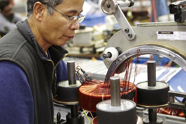
We focus here on toroidal transformers. As the name implies, they have an annular core around which the primary and secondary windings are placed. By contrast, the other forms of isolation transformers employ U-I, E-I and other rectangular shapes.
The big deal about the toroidal transformer core is the absence of core lamination junctions. In ‘run of the mill’ cores, heat and acoustic noise are produced at these junctions.
The principal source of acoustic noise for many transformers is the magneto-striction effect, whereby the individual magnetic domains of the core material are elongated and relaxed alternately by the alternating magnetic flux, producing that irritating 100Hz hum.
In the rolling operations of magnetic core material, the individual magnetic domains (the tiny proto-magnets) are aligned.
When the magnetic flux induced by the coils is in the same direction (zero degrees, as shown in Figure 1), magneto-striction effects are minimised. When the flux is at 90°, as happens in lapped transformer joints, the effects are at a maximum.
It is now readily grasped that the beauty of the toroidal transformer core is the virtually complete alignment throughout the core. It is basically a joint-less continuous strip of core material that’s insulated and wound upon itself.
Diminishing magneto-striction noise is a big advantage, as generally the AV equipment will be close to the isolation transformer.
For pedants, there is still another noise source – the so called Lorentz force effect due to eddy current – but the usual measures taken for sound containment can render this inaudible.
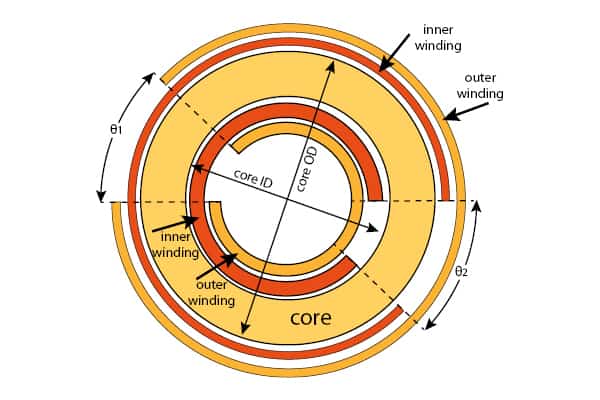
Figure 2
Toroidal transformers as ‘noise’ filters
But there’s more to toroidal transformers – controllable leakage inductance.
Leakage inductance is caused by the interaction of magnetic flux outside the core ‘cutting’ some primary coil winding turns. It can also be a nuisance because it adds impedance to the primary circuit, thereby causing voltage regulation under changing power requirements.
This is generally the case for power transformers.
For an isolation transformer supplying a constant load, leakage inductance can act a low-pass filter, letting through the 50Hz fundamental voltage and basically stopping everything else.
As mentioned, distribution voltage contains a good portion of ‘rubbish’.
Harmonics are generally odd, as evens imply the presence of DC. (Some DC can be present near photovoltaic solar installations.)
There are also inter-harmonics with higher frequencies into the 25kHz region, as well as flicker. The latter, due to switching transients, exhibits very fast rise times, and therefore a very wide frequency spectrum towards 100kHz and higher.
This stuff, if not stopped, is readily conducted and has a long near-field induction effect.
In the toroidal transformer, leakage inductance is controlled by the winding aperture angle (Figure 2) thereby allowing the control of low-pass filter properties.
For power harmonics, a 5% leakage inductance (based on the kVA rating of the transformer) will stop the third and everything above it very nicely.
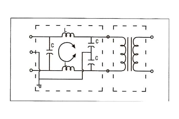
Figure 3
Unlike flicker and harmonics, which are transverse (differential) voltages, the electromagnetic compatibility stuff is common mode and special filtering is needed (Figure 3).
Basically the small toroidal filter provides inductive impedance only to stop common mode noise. The differential signal is passed unimpeded by virtue of the two windings being in opposite phase so that there’s net zero flux contribution in the core. Usually this sort of device is employed in pi filter topology in combination with capacitors.
The Canadian company Torus Power Inc was interviewed for this article. Although not unique in its adoption of toroidal transformers, the company has earned an important market position with its range of AC power supplies.
Torus Power is distributed locally by Network Audio Visual.
Ross Whitney and Kevin Main of Torus Power have confirmed some important construction details. Particularly noteworthy is the performance of the transformer as a filter, in important ways mimicking the performance of the above-mentioned EMC filter.
Using what is termed ‘narrow band technology’, the toroidal transformer offers impressive performance, having a –3dB point at 2kHz, with a roll-off of –30 dB per decade to 20kHz and –60 dB attenuation at 1MHz.
In outline, the tightly controlled equivalent capacitance (reflected from the secondary winding) in combination with the controlled leakage inductance and resistance at the input of the transformer, forms an R-L-C filter with frequency performance as mentioned.
An important aspect of the Torus Power transformer is a very generous core cross-section relative to kVA ratings. The result is low flux density, meaning smaller core losses and linear operation (ie: no third harmonics introduced – this normally occurring because magnetising force H approaches the knee of the hysteresis curve).
Another advantage of the toroidal transformer not immediately recognised is the reduction of parasitic capacitance, and reduced voltage stress on turns with the exception of end turns of the windings.
Note the electric field pictures relevant to rectangular core and a toroidal transformer, as in Figure 4.
Torus Power equipment has a voltage regulator feature, providing 10V taps selected by relays that are controlled from the secondary voltage measurement.
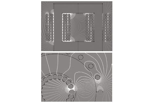
Figure 4
Good grounds
A crucial consideration when installing an isolation transformer is the earth loop impedance – the lower the better.
In Australia all low-voltage distribution is based on multiple earth neutrals (MEN). The ground stake or metallic water pipe connection to the neutral bar is therefore critically important.
An earth loop test needs to be carried out by a licensed electrician. This is a bit tricky, as we’re not talking earth loop impedance for the internal installation (to ensure that earth leakage breakers will trip in the event of earth faults) but the earth loop impedance from the service fuse out.
One alternative (putting faith in the low impedance of the neutral wire) is to do an earth resistance check at the installation ground stake.
As is the practice here, the installation earth in Canada and the United States is at the service entry point.
From there the safety earth wire is pulled through to the metal chassis of connected equipment, and to the metallic cover of the toroidal transformer, as well as to the core and electrostatic shield separating the primary and secondary windings.
The latter is a feature of isolation transformers in general, and basically removes inter-winding capacitance as a feed-through path.
To get the best out of the toroidal core technology, attention to performance-spoiling factors is needed.
Earth loops, although unrelated to transformer hum, can show as hum and therefore star-point equipment signal grounding should be used. The signal grounds for the connected equipment should be located and brought out separately to an insulated ‘grounding’ point, connecting only at one point to the MEN bar.
To end where we began: will we hear the sound of good power quality?
Starting with clean AC is important, but environmental issues such as induction fields from neighbouring equipment and radio frequency interference from other electronic apparatus is equally important.
That said, and in defence of good isolation transformers, power quality in low-voltage distribution isn’t going to get better, particularly because of the increasing penetration of distributed generation – not only solar, but also tri-state generators and other auxiliary and ancillary generators.
One way of avoiding the whole issue is to insert an inline uninterruptible power supply. However, that’s a pricey solution, appropriate perhaps for a server room but not for our AV equipment.
-
ADVERTISEMENT
-
ADVERTISEMENT
-
ADVERTISEMENT
-
ADVERTISEMENT