
What you need to know about speaker wiring
Much is said about the sound quality of speaker wires. Anthony Grimani aims to dispel some common myths and advises on how to properly handle speaker wiring.
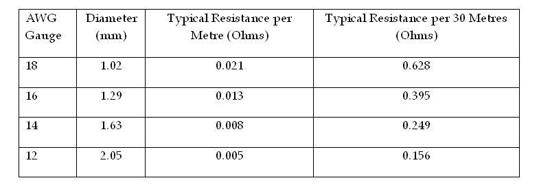
Table 2
There are those who feel that wires need a break-in period. Others feel that solid cores sound better than stranded cores, and others yet say that you need multiple-sized cores so that different frequencies can travel in skin effect over different circumferences.
And then there is one real item that affects the sound of a wire and speaker system combination. The length-related resistance of speaker wires is undeniably audible and you need to consider it in any one of your designs and installations.
ADVERTISEMENT
It starts off with a pretty simple premise. The longer the wire length from amplifier to speaker, the thicker the cable should be. The point is to keep the loop resistance down to below 0.2Ω as a general rule.
Let’s dig in a bit. Speaker cables are mostly copper. Like any other metal, copper is an imperfect conductor, which means that it has some resistance. The amount can be measured per metre; the larger the diameter, the less the resistance per metre (see Table 1).
This resistance, of course, ends up getting in the middle of the connection between your amplifier and your speaker and acting somewhat like a resistor added in the crossover network of your carefully-designed and expensive speakers. That’s not a good idea!
Let’s talk about the input impedance of a speaker. The term impedance is used rather than resistance because the input character of most speakers looks more like a complex combination of resistors, capacitors, and inductors back to the amplifier driving it. This complex load results in a resistance that changes across frequencies. It will go up and down, sometimes varying by a factor of 15:1. I have seen speakers that dip as low as 2Ω and peak up to 30Ω. Figure 1 shows an actual measured impedance curve from a speaker commonly used in high end home cinemas.
So who cares if this curve looks like the elevation profile of a roller coaster at Luna Park? The resistance of the speaker wire that interacts with this variable resistor of the speaker will mess up the frequency response of the incoming signal. Some sounds will be quieter at some frequencies than intended, and the tonal balance will just be plain different from what the speaker designer intended.
If the speaker’s impedance was constant across frequencies, the interaction would be a simple loss of signal, as you can see in Figure 2. Some of the signal is routed down the load and just doesn’t get to the speaker.
You can actually predict how much loss you’ll get by using the equation: Vs=Va x Zs/(Zs+Zw), where Vs is the voltage at the speaker input terminal; Va is the voltage at the amplifier output terminal; Zs is the impedance of the speaker; and Zw is the impedance of the wire.
In addition to the loss of signal voltage at the speaker, you can also get other problems, such as uncontrolled parasitic resonances from the woofers since the cable resistance is acting like a bungee cord between the amplifier and speakers; the amplifier can’t quite control the oscillation of the woofers. The result may be bass that is not as tight as it should be. Bad news!
In reality, since speakers (with rare exception) present resistance values that change across the frequencies of the incoming signal, the loss equation shown above will be different at every frequency. That’s what leads to a very audible shift in the sound of a speaker. If a high quality speaker was designed to have a very pure amplitude and impulse response, it will be significantly degraded to that of a mid-range speaker by speaker wire that is too long for its diameter. What a pity! Your client won’t receive all the potential of quality he or she paid for!
Here is the right way to figure out how to avoid this loss of quality. Ensure that the speaker wire loop resistance is always small enough so that its interaction with the speaker impedance curve is kept to levels below 0.5dB. (The loop resistance is the total resistance of the two legs of the speaker wire pair in series.) In order to do this accurately, you would need to know the actual impedance curve of each speaker model you are specifying into a project, and you would decide on a maximum allowable deviation from ideal response using the equation above.
You can then confirm your calculations by measuring the frequency response of the signal at the speaker terminals with the wire hooked up between it and the amplifier. You can use a spectrum analyser (1/3 octave will suffice), or you can test a number of single tones and measure the resulting voltage at those speaker terminals. You should probably check in 1/3 octave increments. These frequencies would be 20, 25, 31, 40, 50, 63, 80, 100, 125, 160, 200, 250, 315, 400, 500, 630, 800, 1,000, 1,250, 1,600, 2,000, 2,500, 3,150, 4,000, 5,000, 6,300, 8,000, 10,000, 12,500, and 16,000Hz.
I know; that all sounds like a lot of work, and a truly high-end client deserves that you pay so much attention to every little detail, right? In reality, there is a simple set of guidelines. For the vast majority of speakers, if you keep the wire loop resistance to below 0.2Ω, all will be fine. Speakers with higher impedance can be fed with wires that have higher resistance, but again, very few manufacturers of residential speakers will publish the actual impedance curves for you to do precision work. (Note that most commercial speaker manufacturers do publish this piece of info. Go figure; the market that mainly provides basically functional sound gets all the goodies!)
So how do you figure the wire resistance? Ideally, your speaker wire supplier would provide you with the values of resistance per metre.
Wire specification sheets for the commercial and professional world show data for this; why not in the custom install and consumer audio space? You could try asking your vendor and see what they come up with. Otherwise you can follow Table 2, which shows the wire length acceptable for each common gauge of wire.
The wires for surround speakers and subwoofers are shown with more tolerance because absolute accuracy of frequency response isn’t as important with those.
Yes, it’s OK to use thin wire over short lengths. There just isn’t enough resistance build-up over 3m to make any audible difference – unless you want to believe that there are skin effects and other esoteric issues at play, none of which I will chose to contest here as there is a lot more to sound quality than we yet know…
What do you do if you need to go longer than 30m? Don’t use 10 gauge wire, because it is too thick; it starts to be too inductive and will reduce the levels of the high frequencies you will hear. Instead, double up on 12 gauge wire in parallel to get up to 60m for front speakers.
By the same token, if you only have 14 gauge wire in your stores, you can double up on that to get the requisite resistance for 30m.
In fact, I like using wire called 14/4 (four 14 gauge conductors) for best flexibility. You don’t have to jam all the strands into the speaker posts at the end; a 1cm length of reduced diameter won’t make any difference at all. Also, make sure that there aren’t any loose strands at the end that may cause a short circuit, or worse yet an occasional short circuit.
Did you know that two wires that barely touch each other may not conduct at low voltage, but may conduct uni-directionally at higher voltages, acting like a diode? This is not a theory; I have seen this happen! Good luck debugging why the amplifier is sounding funny at higher levels, or worse yet, shutting down every time you want to do an impressive demonstration at high sound pressure levels. That won’t impress anyone at all!
So mind your speaker lengths and diameters, make sure that they are cleanly connected, and while you’re at it make sure that the polarities are all correct. Enjoy the sound.
Anthony Grimani is president of PMI, Ltd., an award-winning home cinema engineering firm, and MSR Acoustics, a manufacturer of fine acoustical tuning systems. MSR is represented in Australia by Wavetrain (www.wavetrain.com.au).
Chase Walton contributed to this column.
-
ADVERTISEMENT
-
ADVERTISEMENT
-
ADVERTISEMENT
-
ADVERTISEMENT