
How do fluorescent lamps work?
In this article, Harry Simidis looks closely at fluorescent lamps and the way they work.
While researching the topic, I came across a very interesting snippet of information by which I was so intrigued that I thought it would be a good way to start.
ADVERTISEMENT
The Lime lighting system was used in theatres in the last half of the 19th century. Lime lighting heated a chunk of limestone by passing three types of burning gasses over it until the limestone glowed bright yellow. The light produced was then focused through lenses and mirrors and directed onto the stage. The phrase “in the limelight” comes from the use of this system. Not only was the limelight system complicated, it also had a habit of burning theatres down.
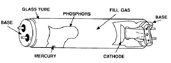
Thankfully we’ve come quite a ways from the days of the limelight system. Modern day fluorescent lighting systems use the phenomenon of phosphorescence which is not to dissimilar to the limelight effect described above. The first fluorescent lamp was patented over 100 years ago by American inventor Peter Cooper Hewitt. Cooper Hewitt’s low pressure mercury arc lamp is the direct parent of today’s modern fluorescent lights. These types of lamps are classified as gas-discharge types because they generate light through the excitation of gasses by passing an electric current through them. A typical fluorescent tube construction is shown in Figure 1.
The lamp shown in Figure 1 is generally how all fluorescent lamps are built be they compact fluorescent (CFL) or linear (LFL) type lamps. All gas discharge lamps have an anode and a cathode.
Electrons always depart the cathode and impact the anode after travelling through the gas lamp, completing the electrical circuit. However, when alternating current is used, the cathode and anode switch roles many times each second (50 times per second, in Australia). When alternating current (AC) is used, the electrical conductors at both ends of the tube are called cathodes. Each of these cathodes is made of coiled tungsten and is coated with a layer of barium, strontium and calcium oxides chosen to have a low thermionic emission temperature.
This allows the cathodes to release more electrons into the gas at lower temperatures and so don’t require too much pre-heating. The gas filling the tube is largely comprised of low pressure mercury vapour with a mixture of argon, xenon, neon or krypton. Light emitting phosphors are applied as a paint-like coating to the inside of the tube. This coating is largely responsible for generating the light we see from a fluorescent lamp. Interestingly, the trace amounts of mercury beads along the inside wall of the tube, when the lamp is cold. During the arcing process, this quickly vaporises and provides the source of short-wave ultra violet radiation (UV) which in turn is absorbed by the phosphor coating to produce visible light. The amount of mercury is minuscule and hence not a cause for concern but should be disposed of appropriately should the lamp ever be damaged or broken.
The process depicted in Figure 2 is typical of how light is generated in a fluorescent lamp. As mentioned earlier, the cathodes emit electrons into the gas. These incident electrons collide with mercury atoms. As a result, kinetic energy is transferred to the atom’s outer electron, causing it to temporarily jump to a higher energy level (or energy band) around the atom. As this higher energy band is unstable, the mercury atom will emit a UV photon as the atom’s electron reverts back to a stable lower energy band. Most of the photons that are released in this way are in the UV region of the spectrum and as such cannot be seen by the human eye. UV photons are then absorbed by electrons in the atoms of the lamp’s interior fluorescent coating, causing a similar energy jump, then drop, with emission of a further photon.
The chemicals that are used to make up the phosphor are chosen so that these emitted photons are in the visible spectrum.
When the light is turned, on the electric current heats up the cathode enough for it to emit electrons. These electrons collide with and ionize noble gas atoms inside the lamp, surrounding the filament to form plasma by the process of impact ionisation. As a result of avalanche ionization the conductivity of the gas rapidly rises, allowing higher current to flow through the lamp. Figure 3 demonstrates this plasma effect, during start-up.
The spectrum of light emitted from a fluorescent lamp is the combination of light directly emitted by the mercury vapour, and by the phosphorescent coating. Nowadays, this internal coating is based on a tri-phosphate mixture of terbium and europium ions to produce light with more natural colour rendering properties.
Figure 4 shows the dominant lighting wavelengths that are emitted by this particular fluorescent light source, having a Correlated Colour Temperature (CCT) in the range of 4,100 Kelvin. Of the wavelengths shown, peaks at indices 2, 4, 5 and 12 appear to dominate the spectrum in terms of intensity. The blue (index 2) and green (4,5) wavelengths are likely generated by the mercury gas vapor and terbium atoms in the doped phosphor coating. The orange-red wavelengths (index 12) are likely generated by the europium atoms in the doped phosphor coating. The reason this light tends to be more palatable to the human eye is because it has colours in the blue and green spectrum to which the cones in our eyes are more sensitive towards. It also has some red which goes towards more closely resembling the colours present in daylight (red, green and blue), with a strong emphasis on blue.
Fluorescent lighting systems need some form of external current regulation to prevent them from self-destructing. Unlike incandescent lamps, if left unregulated the current in a fluorescent lamp would continue to grow until the lamp destroyed itself due to the avalanche ionisation effect described earlier. In addition to current regulation, the lamp also needs a device that starts this arcing effect. Fortunately, the ballast performs all of these functions, and more. All fluorescent lamps need ballasts to work. A ballast is basically a device that stops the flow of current through the lamp from getting out of control. Older magnetic ballasts are comprised of wire wound iron cores and operate the lamps at mains frequency. Newer electronic ballasts perform the same function using electronics at much higher frequencies than 50Hz, at around 20kHz and above. This is done to improve efficiency both in terms of power consumption and light output. Nevertheless, the fluorescent system is still not perfect. By comparison to incandescent lamps that convert only around 5% of their power into visible light (95% into heat and infrared radiation), fluorescent lighting still only converts around 22% to visible light.
The reasons for this sort of efficiency (or inefficiency) can be described by examining typical losses found in a 36W T8 fluorescent lamp as shown in Figure 5. The ballast losses in magnetic ballasts can be as high as 25% of lamp power as compared to 10% in electronic equivalents. The cathodes also consume power in that they need to be heated and hence consume power (8% in this example). Some of the energy in the mercury vapour column is dissipated with only 85% converted to short wave UV and visible light. The phosphor typically has a quantum efficiency of 86%. That means that of the 100 incident UV photons that it receives, it converts only 86 of these to visible light photons.
One of the major reasons that fluorescent and compact fluorescent lighting sources are fast becoming the lamp of choice for consumers is largely due to legislative changes with the recent phasing out of incandescent GLS lamps. This was largely on account of the inefficiency outlined above. In stark contrast to the luminous efficacy (i.e. the amount of light generated per unit of power applied) of around 13 lumens/watt for a 100W 240V GLS lamp, a typical 23W CFL sits around 60 lumens/watt. That’s around 4 to 5 times more efficient. In fact, as a general rule of thumb it’s probably safe to multiply the power rating of a typical CFL purchased at somewhere like Bunnings, by a factor of 5, to determine its rough incandescent power output equivalent.
In conclusion it’s fair to say that fluorescent lamps have come a considerable way over the last few years. There are a number of colour temperatures now available for fluorescent lamps, ranging from warm white (3,000 to 3,500K), cool white (4,100 to 4,200K), full spectrum (4,800 to 5,500K) to daylight (6,000 to 7,000K). Electronic ballasts have introduced further operational efficiencies and are becoming more affordable by the moment. These ballast make dimming possible with digital protocols such DALI (Digital Addressable Lighting Interface), allowing feedback from the ballast back to the facility operator for smoother maintenance and more cost effective operation. Even though fluorescent lighting is still not as efficient as LED lighting, it’s definitely here to stay due to its many benefits not the least of which is cost of ownership over time in addition to energy efficiency.
On a ‘lighter’ note, had our thespian friends of old known about this lighting source back then, imagine the majestic theatres we could have been enjoying to this day..!
Contact
Control Freq
www.controlfreq.com.au
-
ADVERTISEMENT
-
ADVERTISEMENT
-
ADVERTISEMENT
-
ADVERTISEMENT